Prerequisites and Pre-installation Tasks
Compute Node Installation and Boot Media
The installation and boot media is a USB flash drive. There are two types of USB images:
| Image name | USB size | Description |
esdc-<edition>-hn-<version>.img.gz |
6 GB | Used for installation of the first compute node. |
esdc-<edition>-cn-<version>.img.gz |
2 GB | Used for installation of any other compute node. |
Note
The first compute node image is just a reqular compute node that includes Danube Cloud service virtual machines.
The current version of both media can be downloaded from: https://github.com/erigones/esdc-ce/wiki/Download
In the file notes-x.y.z.txt, you can find SHA1 checksums of both images and an automatically generated root password needed for recovery purposes and single user mode, respectively.
It is recommended to use two identical USB flash drives simultaneously in case one of them would fail.
Creating a Bootable USB Flash Drive
Warning
Incorrect procedure of creating a USB flash drive can cause data loss!
Warning
Before writing anything to the USB flash drive, make sure that it does not contain any important data. The image copying procedure destroys all contents of the USB flash drive.
Linux
# Unpack the gzip archive:
gunzip esdc*.img.gz

# Copy the image file onto the USB flash drive:
dd bs=1M if=esdc*.img of=/dev/sdX
Mac OS X
# Determine the device identifier of the USB flash drive:
diskutil list

/dev/disk3
#:  TYPE NAME                    SIZE       IDENTIFIER
0:  FDisk_partition_scheme       2.0 GB     disk3
1:  DOS_FAT_32                   2.0 GB     disk3s1


# Unmount the USB flash drive:
diskutil unmountDisk /dev/disk3

# Unpack the gzip archive:
gunzip esdc*.img.gz

# Copy the image file onto the USB flash drive:
# (To achieve faster data transfer, use the device
# identifier /dev/rdiskX instead of /dev/diskX.)
sudo dd bs=1m if=esdc*.img of=/dev/rdisk3
Windows
- Unpack the gzip archive
esdc*.img.gz. If necessary, install a free and open source application 7-Zip, which is capable of handling archives in gzip format. - Install an open source utility win32diskimager or Rufus designed for writing disk images to USB flash drives.
- Insert the USB flash drive.
- Write the unpacked
esdc*.imgimage file to the USB flash drive.
- Unpack the gzip archive
Compute Node Factory Reset
A reinstall requires the zones zpool to be removed from local disks before proceeding. This can be done in one of the following ways:
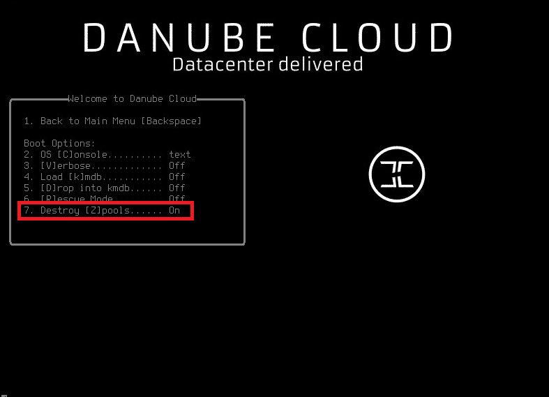
- Set Destroy zpools -> On in the boot loader options. You can see boot options in menu by pressing
4and then7when the boot loader appears. After the change, confirm settings by pressing1(go back) and boot by pressing1orEnter. The compute node will continue to boot up and the zones zpool will be destroyed before new clean install. - Manually formatting the hard drives which are used for the zones zpool. This can be done directly through the embedded RAID management of the server which is available when the server boots up.
Warning
Boot option Destroy zpools destroys all zpools on a machine so make sure you don’t need any data before proceeding.
Note
To see Destroy zpools boot option, you have to boot from an USB stick. It is not available from hard disk boot menu (you simply cannot destroy the zpool you are booting from).
Preparing your Network Infrastructure
Danube Cloud utilizes a concept of virtual networks. A virtual network is a logically separated subnet that allows virtual machines to connect to the external networks (e.g. internet) or to communicate internally within the Danube Cloud data center.
There is one special virtual network called admin that is used for internal purposes. During the installation of the compute node, you will be asked for information about this network. The admin network requires access to the internet. It should be a full /24 subnet (256 IP addresses) and cannot be smaller than a /26 subnet (64 IP addresses).
Using of VLANs for virtual networks is recommended as it ensures virtual networks separation. You can either use a separate physical interface (or interfaces aggregated with LACP) for the admin network, or you can use VLANs to separate the networks on the same physical link. This also allows you to create a lot more virtual networks in the Danube Cloud installation.
See also
For more information on how to setup virtual networks and their connection to the physical interfaces please see a separate chapter about networking
If you don’t have an appropriate hardware router or firewall, you can create one virtual server inside Danube Cloud (e.g. SunOS Zone) with two network interfaces - internal and external - and setup it to serve as a network router for your internal subnets (virtual networks). You can follow our guide how to create an access zone.
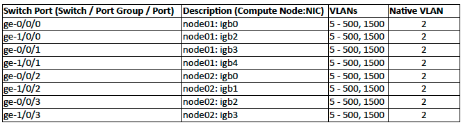
Below is an example port map for interconnection of two Danube Cloud compute nodes using two stacked switches, VLANs for virtual networks, link aggregations for speed and redundancy and with the admin virtual network as a native VLAN.
BIOS Configuration
The following settings should be configured in BIOS configuration of your compute node (if available):
Enable hardware virtualization (VT-x) support.
Warning
Hardware virtualization support must enabled at least on the first compute node.
Enable ACPI SRAT. If ACPI SRAT is not available in your BIOS configuration, disable NUMA/Node interleaving. Otherwise the following message may appear during boot time:
WARNING: Couldn't read ACPI SRAT table from BIOS. lgrp support will be limited to one group.
Disable CPU C-States.
Note
Some Intel® processors, which are using the C-States feature can cause an error that may seriously endanger correct functioning of a compute node. The error is treated in the system, but you are advised to disable C-States in the BIOS configuration.
Disable USB 3 support if you cannot boot from the USB stick.
Warning
USB version 3 is supported but on some hardware it may cause the operating system initialization to fail.
IPMI over LAN / Serial Redirect
The compute node can be easily accessed remotely through a serial console. It is necessary to allow IPMI over LAN and Serial Redirection in the BIOS configuration.
# Log in to the serial console by using the ipmitool command-line utility:
ipmitool -I lanplus -U <USER> -H <IP> -P<PASSWORD> sol activate